While working on a recent hybrid GCP plus on-premise customer architecture, we had a need to connect GKE cluster running in GCP to a service running in on-premise through a VPN. There were few unique requirements like needing to expose only a small IP range to the on-premise and having full control over the IP addresses exposed. In this blog, I will talk about the different approaches possible from a networking perspective when connecting GKE cluster to a on-premise service. Following options are covered in this blog:
- Flexible pod addressing scheme
- Connecting using NAT service running on VM
- Using IP masquerading at the GKE node level
I did not explore Cloud NAT managed service as that works only with private clusters and it does not work through VPN. I have used VPC native clusters as that has become the default networking scheme and it is more straightforward to use than route-based clusters. For more information on VPC native clusters and IP aliasing, please refer to my earlier blog series here.
Requirements
Following was the high level architecture:

On-premise application is exposing the service on a specific tcp port that we needed to access from the pods running in GKE cluster. We had a need to expose only few specific GCP ip addresses to on-premise.
For this use-case, I have used VPN using dynamic routing. There is a need to open up the firewall in on-premise for the source ip addresses that are accessed from GCP. To try this example where you don’t have on-premise network, you can setup 2 VPCs and make one to simulate on-premise.
Flexible pod addressing scheme
In VPC native clusters, there are separate IP address ranges allocated for GKE nodes, pods and services. The node ip address is allocated from the VPC subnet range. There are 2 ways to allocate ip addresses to pods and services.
GKE managed secondary address
In this scheme, GKE manages secondary address ranges. When the cluster is created, GKE automatically creates 2 IP alias ranges, 1 for the pods and another for the services. The user has a choice to enter the IP address range for the pods and services or let the GKE pickup the address ranges. Following are the default, minimum and maximum subnet range sizes for the pods and services.
| Default | Minimum | Maximum | |
| Pods | /14 (2^18 pod ip address) | /9 (2^23 pod ip address) | /21 (2^11 pod ip address) |
| Services | /20 (2^12 service ip address) | /16 (2^16 service ip address) | /27 (2^5 service ip address) |
There is another important parameter called number of pods per node. By default, GKE reserves a /24 block or 256 ip addresses per node. Considering ip address reuse among pods when pods gets autoscaled, 110 pods share the 256 ip addresses and so the number of pods per node is set by default to 110. This number can be user configured.
For example, taking /21 for pods, we can have a total of 2048 pods. Assuming default of 110 pods(/24 address range for pods) in each node, then we can have only a maximum of 2^(24-21) = 8 nodes. This limit is irrespective of the subnet range reserved for the nodes. If we reduce the number of ip addresses for pods per node to 64(/26 range), then we can have a maximum of 2^(26-21)=32 nodes.
User managed secondary address
For my use case, GKE managed secondary address did not help since the minimal pod ip range is /21 and the customer was not willing to expose a /21 ip range in their on-premise firewall. The customer was willing to provide a /25 or /27 ip range to the pods. We settled on the configuration below:
- /25 range for the pods, 8 pods per node. /25 range would give us 128 pod addresses. 8 pods per node would need 16 ip address(4 bits) per node. This provided us 2^(7-4)=8 nodes maximum in the cluster.
- /27 range for the services. It was not needed to expose the service ip range to the on-premise as service ip addresses are used more for egress from on-premise.
- /27 range for the nodes. Even though we could have created 32 nodes with this range, we are limited to 8 nodes because of the first point above.
Following are the steps to create a cluster with user managed secondary address:
- Create ip alias range for pods and services from the VPC section in the console
- When creating cluster, disable option “automatically create secondary range” and select pre-created ip alias range for the pods and services.
- Set maximum number of pods per node to 8.
Following picture shows the 2 ip alias addresses created along with the VPC subnet:

Following picture shows the networking section of cluster creation part where we have specified the primary and secondary ip ranges for pod and service ip addresses.

Connecting using NAT service running on VM
Rather than exposing individual pod ip address to the on-premise service, we can expose a single IP address using a NAT service running in GCP. With this approach, all the pod IP addresses gets translated to the single NAT IP address. We only need to expose the single NAT ip address to the on-premise firewall.
Following picture shows how the architecture would look:
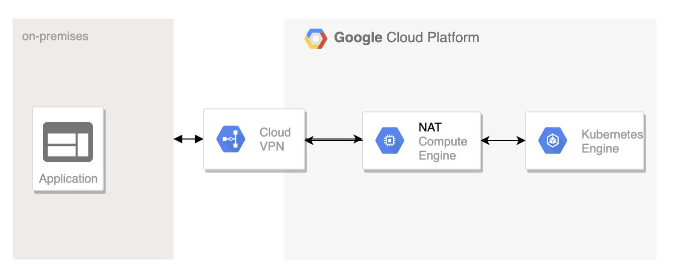
Following are the steps needed:
- Create NAT instance on compute engine. As I mentioned earlier, Cloud NAT managed service could not be used as its not integrated with VPN. We can either create a standalone NAT instance or HA NAT instance as described here.
I used the following command to create NAT instance:
 gcloud compute instances create nat-gateway --network gcp-vpc \
     --subnet subnet-a \
     --can-ip-forward \
     --zone us-east1-b \
     --image-family debian-9 \
     --image-project debian-cloud \
     --tags nat
- Login to the NAT instance and setup iptables rules to setup the NAT.
sudo sysctl -w net.ipv4.ip_forward=1
sudo iptables -t nat -A POSTROUTING -o eth0 -j MASQUERADEsudo sysctl -w net.ipv4.ip_forward=1
- Create GKE cluster with network tag. I was not able to use network tag for creating GKE cluster from the console and the only way is to to use gcloud CLI. The network tag is needed so that the route entry to forward to NAT applies only to the instances that are part of the GKE cluster.
gcloud container clusters create mygcpr-cluster --tags use-nat \
 --zone us-east1-b \
 --network gcp-vpc --subnetwork subnet-a --enable-ip-alias
- Create route entry to forward traffic from GKE cluster destined to on-premise service through the NAT gateway. Please make sure that the priority of this route entry supersedes other route entries. (Please note that the priority increase is in reverse, lower number means higher priority)
gcloud compute routes create nat-vpn-route1 \
     --network gcp-vpc \
     --destination-range 192.168.0.0/16 \
     --next-hop-instance nat-gateway \
     --next-hop-instance-zone us-east1-b \
     --tags use-nat --priority 50
To test this, I created a pod on the GKE cluster and tried to ping a on-premise instance and with “tcpdump” verified that the source ip address of the ping request is not a pod IP but the NAT gateway IP address.
Using masquerading at the GKE node
The alternative to use NAT gateway is to do masquerading at the node level. What this will do is to translate the pod ip address to the node ip address when packets egress from the GKE node. With this case, it is needed to expose only the node IP addresses to on-premise and it’s not needed to expose pod ip addresses. There is a masquerading agent that runs in each GKE node to achieve this.
Following are the steps to setup masquerading:
- The 2 basic requirements for masquerading agent to run in each node is to enable network control policy and have the pod ip address outside the RFC 1918 ip address range 10.0.0.0/8. Network control policy can be enabled when creating GKE cluster.
- By default, masquerading is setup to avoid masquerading rfc 1918 addresses(10.0.0.0/8, 192.168.0.0/16, 172.16.0.0/12) as well as link local address(169.254.0.0/16). This can be overridden by the use of config file at the cluster level.
- When there is a change in config file, the agent at the node periodically reads the config level and updates the cluster. This interval can also be configured.
Following is the config file I used:
nonMasqueradeCIDRs:
resyncInterval: 60s
masqLinkLocal: true
In my case, since I used rfc 1918 address for my pod, I wanted those ip addresses to be also masqueraded. The config file works in a negative direction w.r.to specifying ip address. Since I have not specified any ip address, all rfc1918 address will get masqueraded with this configuration. You can add specific ip address that you do not want masquerading to happen.
To apply the config, we can use the following kubectl command:
kubectl create configmap ip-masq-agent --from-file config --namespace kube-system
In the customer scenario, we have gone with user managed secondary address and that worked fine. The other 2 options I described above would also have worked. We hit few other issues with GCP VPN working with Cisco ASA which we were able to eventually overcome, more details on a different blog…

We have explored sometime back masquerading option and it was working fine in our test case.
Ok, good to know.
Thank You for post, It is very help full. I am trying to simulate setup, running in to issues when testing from GKE to on-prem. please let me know once cloud VPN is set up, what are the FW rules needs to added on both ends(GCP and on-prem).
Thank you so much for this post, helped a lot to set vpn from gke to on-prem device